Kelvin (Revision B)
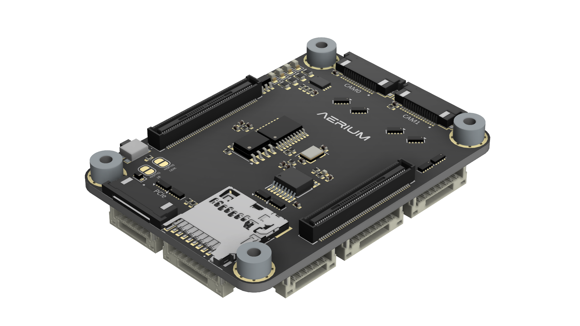
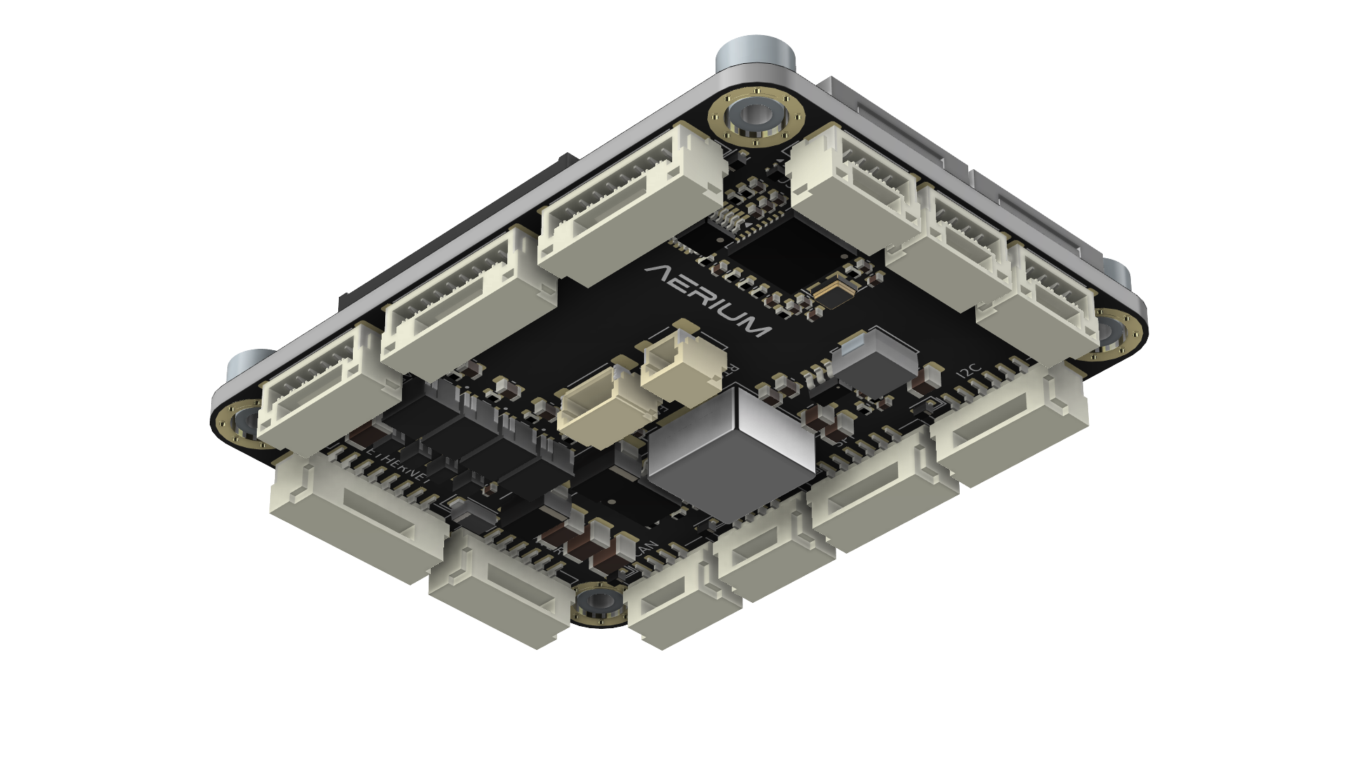
The Aerium Kelvin is an advanced carrier board engineered to unlock the full potential of the Raspberry Pi Compute Module 5 (CM5) in compact, performance-driven systems. Designed for unmanned platforms and embedded computing applications, Kelvin combines robust processing capabilities with a broad connectivity suite in a lightweight, space-efficient form factor.
General
- The Kelvin introduces a powerful, yet efficient and compact edge computing solution based on Raspberry pi compute modules.
- Kelvin introduces rich set of interfaces while maintain small footprint and minimal weight.
- The board is especially designed for unmanned systems and other space and volume constrained implementations.
Compatibility
-
The Kelvin introduces a powerful, yet efficient and compact edge computing solution based on Raspberry pi compute modules:
- Raspberry Pi Compute Module 5 (EMMC versions only)
- Note: since Pi CM4 and Pi CM5 are mostly similar there is also partial compatibility to Pi CM4
Resources
Mechanical
-
Weight
- Empty weight (w/o Compute Module): ~14 [g].
- Raspberry pi weight (w/o heatsink): ~8 [g].
- Heatsink: ~50 [g].
- Total Weight: ~72 [g].
-
Dimensions
- Board dimensions are defined in millimeters.
- Mounting hole size is M2.5.

Electrical
General
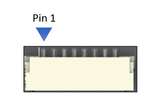
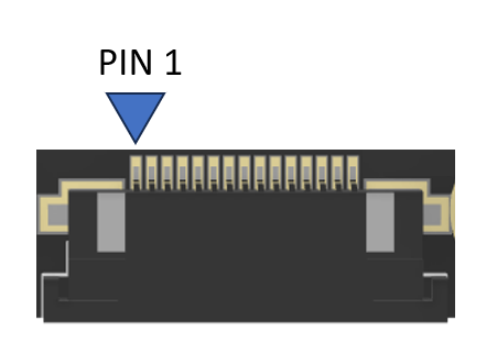
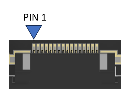
- For each connector specification, the pinout orientation is determined by an arrow pointing to pin 1.
Specifications
-
Input voltage: 8-60 [V]
-
GPIO / Communication logic level: 3.3 [V]
- Warning: do not operate at any other logic voltage level.
-
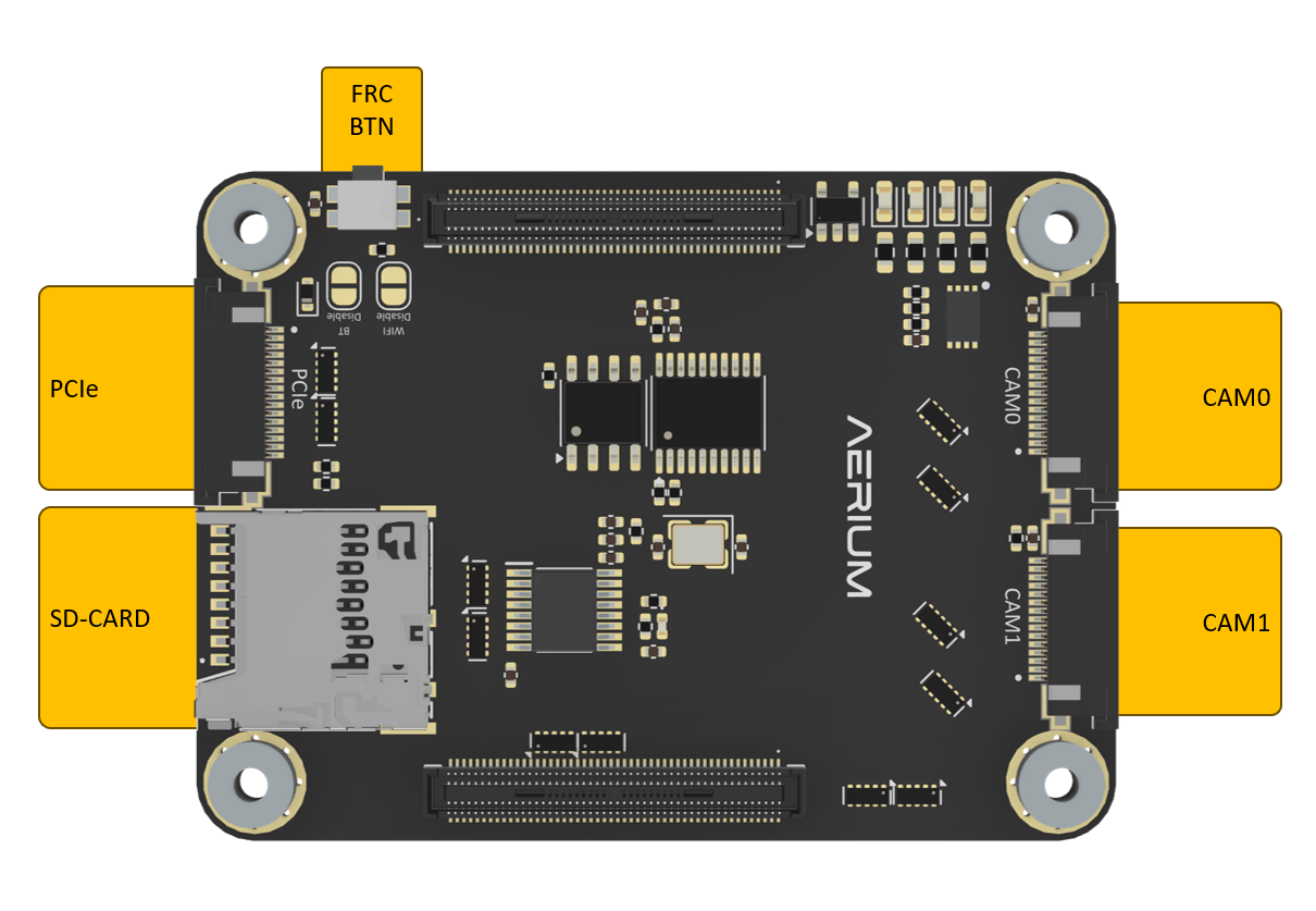
Top View
-
Bottom View
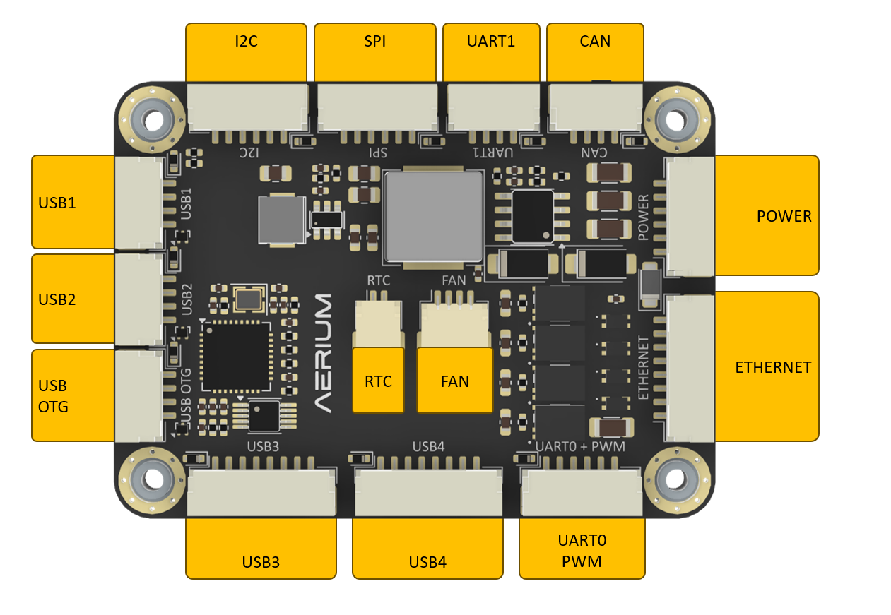
Electrical pinout
-
Connector orientation
- JST-GH cables shall be oriented according to the illustration
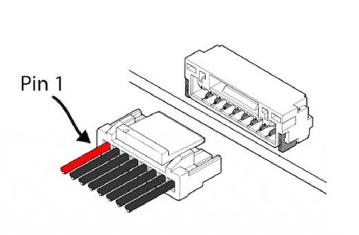
- JST-GH cables shall be oriented according to the illustration
FRC Button

- To flash Raspberry pi compute module, use the FRC button according to the following steps:
- Power off the board
- hold the FRC button
- Power up the board
- release the FRC button
- The Raspberry pi compute modules is now in recovery mode
- run the script on the host pc to enable flashing
Power

-
Connector Definition
Type Part Number Part Name Board Connector SM06B-GHS-TBT JST-GH Cable Connector GHR-06V-S JST-GH -
Connector Pinout
Pin Name Description Voltage 1 VIN Voltage Input 8V - 60V 2 VIN Voltage Input 8V - 60V 3 VIN Voltage Input 8V - 60V 4 GND Ground GND 5 GND Ground GND 6 GND Ground GND
USB OTG

-
Connector Definition
Type Part Number Part Name Board Connector SM04B-GHS-TB JST-GH Cable Connector GHR-04V-S JST-GH -
Connector Pinout
Pin Name Description Voltage 1 OTG 5V Power Input USB OTG Power Supply 5V 2 USB0_D- USB Data Minus 3.3V 3 USB0_D+ USB Data Plus 3.3V 4 GND Ground GND
USB1
-
Connector Definition
Type Part Number Part Name Board Connector SM04B-GHS-TB JST-GH Cable Connector GHR-04V-S JST-GH -
Connector Pinout
Pin Name Description Voltage 1 Power Output USB Power Supply 5V 2 USB0_D- USB Data Minus 3.3V 3 USB0_D+ USB Data Plus 3.3V 4 GND Ground GND
USB2
-
Connector Definition
Type Part Number Part Name Board Connector SM04B-GHS-TB JST-GH Cable Connector GHR-04V-S JST-GH -
Connector Pinout
Pin Name Description Voltage 1 Power Output USB Power Supply 5V 2 USB0_D- USB Data Minus 3.3V 3 USB0_D+ USB Data Plus 3.3V 4 GND Ground GND
USB3
-
Connector Definition
Type Part Number Part Name Board Connector SM08B-GHS-TB JST-GH Cable Connector GHR-08V-S JST-GH -
Connector Pinout
Pin Name Description Voltage 1 Power Output USB Power Supply 5V 2 USB_D_N (USB2.0) USB 2.0 Data Minus 3.3V 3 USB_D_P (USB2.0) USB 2.0 Data Plus 3.3V 4 USBSS_TX_N SuperSpeed TX Minus 3.3V 5 USBSS_TX_P SuperSpeed TX Plus 3.3V 6 USBSS_RX_N SuperSpeed RX Minus 3.3V 7 USBSS_RX_P SuperSpeed RX Plus 3.3V 8 GND Ground GND
USB4
-
Connector Definition
Type Part Number Part Name Board Connector SM08B-GHS-TB JST-GH Cable Connector GHR-08V-S JST-GH -
Connector Pinout
Pin Name Description Voltage 1 Power Output USB Power Supply 5V 2 USB_D_N (USB2.0) USB 2.0 Data Minus 3.3V 3 USB_D_P (USB2.0) USB 2.0 Data Plus 3.3V 4 USBSS_TX_N SuperSpeed TX Minus 3.3V 5 USBSS_TX_P SuperSpeed TX Plus 3.3V 6 USBSS_RX_N SuperSpeed RX Minus 3.3V 7 USBSS_RX_P SuperSpeed RX Plus 3.3V 8 GND Ground GND
UART0 + PWM
-
Connector Definition
Type Part Number Part Name Board Connector SM06B-GHS-TB JST-GH Cable Connector GHR-06V-S JST-GH -
Connector Pinout
Pin Name Description Voltage 1 Power Output Power Supply 5V 2 UART0_TX UART0 Transmit 3.3V 3 UART0_RX UART0 Receive 3.3V 4 PWM0_0 / UART4_TX PWM0_0 or UART4 TX 3.3V 5 PWM0_1 / UART4_RX PWM0_1 or UART4 RX 3.3V 6 GND Ground GND
UART1
-
Connector Definition
Type Part Number Part Name Board Connector SM04B-GHS-TB JST-GH Cable Connector GHR-04V-S JST-GH -
Connector Pinout
Pin Name Description Voltage 1 Power Output Power Supply 5V 2 UART2_TXD UART2 Transmit 3.3V 3 UART2_RXD UART2 Receive 3.3V 4 GND Ground GND
Ethernet
-
Connector Definition
Type Part Number Part Name Board Connector SM08B-GHS-TB JST-GH Cable Connector GHR-08V-S JST-GH -
Connector Pinout
Pin Name Description Voltage 1 ETH_MDI0_P Ethernet Pair 0 Positive - 2 ETH_MDI0_N Ethernet Pair 0 Negative - 3 ETH_MDI1_P Ethernet Pair 1 Positive - 4 ETH_MDI1_N Ethernet Pair 1 Negative - 5 ETH_MDI2_P Ethernet Pair 2 Positive - 6 ETH_MDI2_N Ethernet Pair 2 Negative - 7 ETH_MDI3_P Ethernet Pair 3 Positive - 8 ETH_MDI3_N Ethernet Pair 3 Negative -
CAN
-
Connector Definition
Type Part Number Part Name Board Connector SM04B-GHS-TB JST-GH Cable Connector GHR-04V-S JST-GH -
Connector Pinout
Pin Name Description Voltage 1 Power Output Power Supply 5V 2 CAN_H CAN High 3.3V 3 CAN_L CAN Low 3.3V 4 GND Ground GND
I2C
-
Connector Definition
Type Part Number Part Name Board Connector SM06B-GHS-TBT JST-GH Cable Connector GHR-06V-S JST-GH -
Connector Pinout
Pin Name Description RPI Name Voltage 1 Power Output Power Supply - 5V 2 I2C0_SCL I2C0 Serial Clock Pin 80 / I2C6_SCL / GPIO 39 3.3V 3 I2C0_SDA I2C0 Serial Data Pin 82 / I2C6_SDA / GPIO 38 3.3V 4 I2C1_SCL I2C1 Serial Clock Pin 35 / I2C0_SCL / GPIO 1 3.3V 5 I2C1_SDA I2C1 Serial Data Pin 36 / I2C0_SDA / GPIO 0 3.3V 6 GND Ground - GND
SPI
-
Connector Definition
Type Part Number Part Name Board Connector SM06B-GHS-TBT JST-GH Cable Connector GHR-06V-S JST-GH -
Connector Pinout
Pin Name Description Voltage 1 Power Output Power Supply 5V 2 SPI0_SCLK SPI Serial Clock 3.3V 3 SPI0_MISO SPI Master In Slave Out 3.3V 4 SPI0_MOSI SPI Master Out Slave In 3.3V 5 SPI0_CS0_N SPI Chip Select 0 3.3V 6 GND Ground GND
CAM0 (MIPI-CSI)
-
Connector Definition
Type Part Number Board Connector SFV15R-1STBE1HLF Cable Connector FFC 15 PIN 0.5mm pitch -
Connector Pinout
Pin Name Description Voltage 1 GND Ground GND 2 CSI0_D0_N Camera Data Lane 0 Negative 1.2V 3 CSI0_D0_P Camera Data Lane 0 Positive 1.2V 4 GND Ground GND 5 CSI0_D1_N Camera Data Lane 1 Negative 1.2V 6 CSI0_D1_P Camera Data Lane 1 Positive 1.2V 7 GND Ground GND 8 CSI0_CLK_N Camera Clock Negative 1.2V 9 CSI0_CLK_P Camera Clock Positive 1.2V 10 GND Ground GND 11 CAM0_PWDN Camera Power Down 3.3V 12 CAM0_MCLK Camera Master Clock 3.3V 13 CAM0_SCL Camera I2C Serial Clock 3.3V 14 CAM0_SDA Camera I2C Serial Data 3.3V 15 3.3V Power Supply 3.3V
CAM1 (MIPI-CSI)
-
Connector Definition
Type Part Number Board Connector SFV15R-1STBE1HLF Cable Connector FFC 15 PIN 0.5mm pitch -
Connector Pinout
Pin Name Description Voltage 1 GND Ground GND 2 CSI2_D0_N Camera Data Lane 0 Negative 1.2V 3 CSI2_D0_P Camera Data Lane 0 Positive 1.2V 4 GND Ground GND 5 CSI2_D1_N Camera Data Lane 1 Negative 1.2V 6 CSI2_D1_P Camera Data Lane 1 Positive 1.2V 7 GND Ground GND 8 CSI2_CLK_N Camera Clock Negative 1.2V 9 CSI2_CLK_P Camera Clock Positive 1.2V 10 GND Ground GND 11 CAM1_PWDN Camera Power Down 3.3V 12 CAM1_MCLK Camera Master Clock 3.3V 13 CAM1_SCL Camera I2C Serial Clock 3.3V 14 CAM1_SDA Camera I2C Serial Data 3.3V 15 3.3V Power Supply 3.3V
PCIe
-
Connector Definition
Type Part Number Board Connector SFV16R-1STBE1HLF Cable Connector FFC 16 PIN 1.0mm pitch -
Connector Pinout
Pin Name Description Voltage 1 5V Power Supply 5V 2 5V Power Supply 5V 3 GND Ground GND 4 PCIE_CLK_P PCIe Clock Positive 1.2V 5 PCIE_CLK_N PCIe Clock Negative 1.2V 6 GND Ground GND 7 PCIE_RX_P PCIe Receiver Positive 1.2V 8 PCIE_RX_N PCIe Receiver Negative 1.2V 9 GND Ground GND 10 PCIE_TX_P PCIe Transmit Positive 1.2V 11 PCIE_TX_N PCIe Transmit Negative 1.2V 12 GND Ground GND 13 PCIE_PWR_EN PCIe Power Enable 3.3V 14 PCIE_DET_WAKE PCIe Detect / Wake 3.3V 15 PCIE_CLKREQ_N PCIe Clock Request 3.3V 16 PCIE_RST_B PCIe Reset 3.3V
RTC
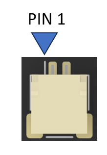
-
Connector Definition
Type Part Number Part Name Board Connector SM02B-SRSS-TB JST SH 1.0 mm SMT Side-Entry Header Cable Housing SHR-02V-S JST SH 2-Circuit Receptacle Housing Crimp Terminal SSHL-002T-P0.2 JST SH Crimp Contact (AWG 32–28) -
Connector Pinout
Note: This pinout is non-standard and was designed to match the official Raspberry Pi 5 RTC battery connectorPin Name 1 GND 2 RTC Power Input
FAN
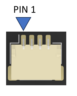
-
Connector Definition
Type Part Number Part Name Board Connector SM04B-SRSS-TB JST SH 1.0 mm SMT Side-Entry Header Cable Housing SHR-04V-S JST SH 4-Circuit Receptacle Housing Crimp Terminal SSHL-004T-P0.2 JST SH Crimp Contact (AWG 32–28) -
Connector Pinout
Pin Name 1 5v 2 PWM 2 GND 2 TACHO
SD-Card
- General
- The SD card slot is for storage only and doesn’t support flashing an operating system.
Software
General
- The software installation for the Kelvin board is simple and based on the same steps as the Dev Kit board.
Flashing Raspbian OS
- Step 1: Hold the FRC button and power up the Kelvin board.
- Step 2: Hold the FRC button for additional 3 seconds after power up and release.
- Step 3: Connect a USB cable to USB OTG port.
- Step 4: Flash the module using the instructions in the following link: https://www.raspberrypi.com/documentation/computers/compute-module.html#flash-compute-module-emmc
- Step 5: When installation is complete, reboot the board.
Serial Port Mapping and Configuration
| Physical Port Name | Linux Device Name | CM5 GPIO | CM5 UART Name | Required Overlay |
|---|---|---|---|---|
| UART0 | /dev/ttyAMA0 | RX: 15 TX: 14 | UART0 | uart0-pi5 |
| UART0 | /dev/ttyAMA4 | RX: 13 TX: 12 | UART4 | uart4-pi5 |
| UART1 | /dev/ttyAMA2 | RX: 5 TX: 4 | UART2 | uart2-pi5 |
Enabling UART0 and UART1 ports on Raspberry Pi CM5
- Step 1: Power off the Raspberry Pi CM5 board.
- Step 2: Mount the
/boot/firmwarepartition of the eMMC. - Step 3: Open the file
/boot/firmware/config.txt. - Step 4: Add the following lines at the end of the file:
NOTE: uart4 will be used on the PWM pins on port UART0
dtoverlay=uart0-pi5
dtoverlay=uart2-pi5
dtoverlay=uart4-pi5 - Step 5: Reboot the board.
Adding Static IP Configuration to Raspberry Pi CM5
- Step 1: Power off the Raspberry Pi CM5 board.
- Step 2: Mount the
/boot/firmwarepartition of the eMMC. - Step 3: Open the file
/boot/firmware/cmdline.txt. - Step 4: Locate the single long line of kernel parameters (do not add line breaks).
- Step 5: Append the following to the end of that line, separated by a space:
ip=192.168.55.10::192.168.1.1:255.255.255.0::eth0:off - Step 5: Reboot the board.
Enabling Dual MIPI IMX219 Cameras on Raspberry Pi CM5
- Step 1: Power off the Raspberry Pi CM5 board.
- Step 2: Mount the
/boot/firmwarepartition of the eMMC. - Step 3: Open the file
/boot/firmware/config.txt(orusercfg.txtif your OS expects custom edits there). - Step 4: Add the following lines at the end of the file:
# Enable camera firmware support
start_x=1
gpu_mem=256

# Enable dual IMX219 cameras (Pi Camera V2 modules)
dtoverlay=imx219,cam0
dtoverlay=imx219,cam1 - Step 5: Reboot the board.
Enabling CAN interface on Raspberry Pi CM5
- The MCP2515 is connected to SPI1 with CS0 (GPIO18) on the CM5.
- Step 1: Power off the Raspberry Pi CM5 board.
- Step 2: Mount the
/boot/firmwarepartition of the eMMC. - Step 3: Open the file
/boot/firmware/config.txt - Step 4: Add the following line to the end of the file:
dtparam=spi=on
dtoverlay=spi1-1cs
dtoverlay=mcp2515,spi1-0,oscillator=8000000,interrupt=25 - Step 5: Reboot the board.