Logix
The Logix is a compact dual FT4232H-based M.2 Key-B expansion module providing both high-speed USB-UART and GPIO/MPSSE functionality in a single 3042-form-factor card. Designed for embedded and industrial systems, Logix enables seamless multi-channel serial communication and flexible digital I/O control via USB, making it ideal for automation, debugging, and prototyping applications.

General
- Integrated Microchip USB2517 high-speed 7-port USB 2.0 hub
- Acts as the central USB hub controller for all onboard devices
- Routes data to both FT4232H controllers and external downstream ports
- Dual FT4232H USB interface controllers (connected via USB2517)
- One dedicated to UART-to-USB conversion (4 ports)
- One dedicated to GPIO / MPSSE functions (4 channels)
- M.2 Key-B 3042 form factor
- Provides a total of:
- 4× UART interfaces
- 4× USB downstream ports
- 16× GPIO / MPSSE-capable lines
- Supports USB 2.0 High-Speed (480 Mbps) operation
- Ideal for embedded PCs, industrial control, and hardware testing
Mechanical
- Dimensions: 30 × 42 mm (M.2 3042 Key-B)
- Mounting: Single-screw M.2 retention
- Weight: ~10 g
Resources
Electrical
General
- USB topology:
The USB2517 hub interfaces directly with the M.2 USB upstream connection and distributes bandwidth to both FT4232H controllers and the external USB outputs. - Supply voltage: 3.3 V from M.2 slot
- Logic voltage (I/O): 3.3 V TTL compatible
-
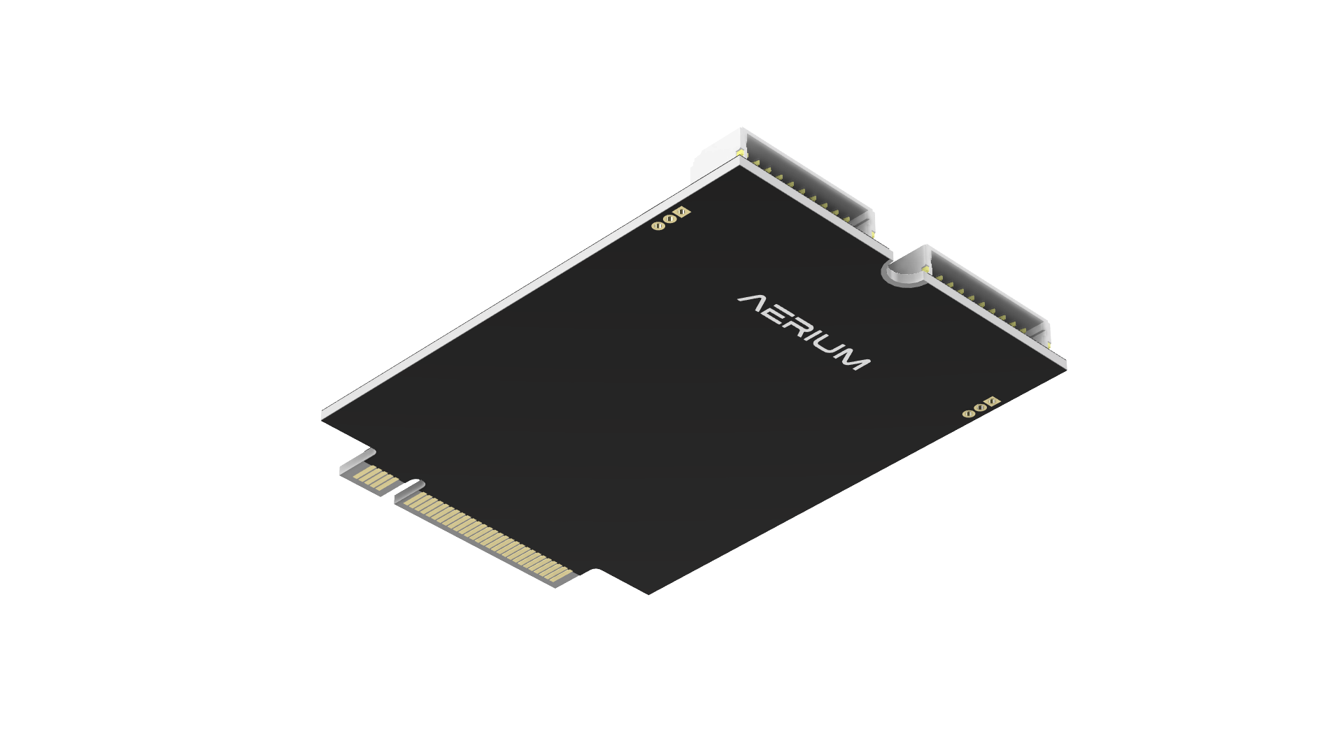
Top View
-
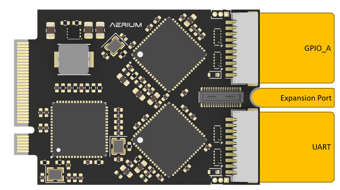
Breakout Board View
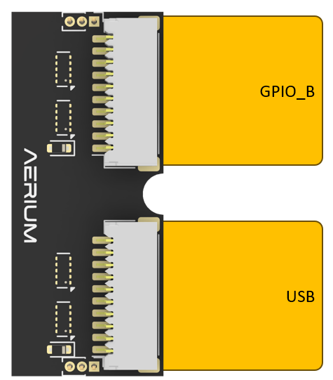
-
Stackup View
Note: The current stack-up expansion is recommended for development use only.
For production deployment, a more robust mechanical design and mounting solution is required.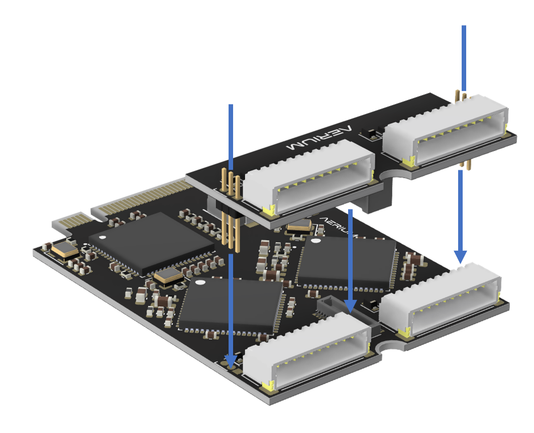
-
Specifications
- Interfaces:
- Microchip USB2517 – 7-port USB 2.0 hub (1 upstream, 6 downstream used)
- Dual FT4232H – connected to hub for UART and GPIO/MPSSE
- USB standard: USB 2.0 High-Speed (480 Mbps)
- ESD protection on all USB and GPIO lines
UART Connector
-
Connector Definition
Type Part Number Series Board Connector SM10B-SRSS-TB JST-SH Cable Connector SHR-10V-S-B JST-SH -
Connector Pinout
Pin Name Description 1 5V Power output (5 V) 2 TX1 UART 1 TX (3.3 V) 3 RX1 UART 1 RX (3.3 V) 4 TX2 UART 2 TX (3.3 V) 5 RX2 UART 2 RX (3.3 V) 6 TX3 UART 3 TX (3.3 V) 7 RX3 UART 3 RX (3.3 V) 8 TX4 UART 4 TX (3.3 V) 9 RX4 UART 4 RX (3.3 V) 10 GND Ground
GPIO_A Connector
-
Connector Definition
Type Part Number Series Board Connector SM10B-SRSS-TB JST-SH Cable Connector SHR-10V-S-B JST-SH -
Connector Pinout
Pin Name Description 1 5V Power output (5 V) 2 GPIO1 GPIO 1 (3.3 V) 3 GPIO2 GPIO 2 (3.3 V) 4 GPIO3 GPIO 3 (3.3 V) 5 GPIO4 GPIO 4 (3.3 V) 6 GPIO5 GPIO 5 (3.3 V) 7 GPIO6 GPIO 6 (3.3 V) 8 GPIO7 GPIO 7 (3.3 V) 9 GPIO8 GPIO 8 (3.3 V) 10 GND Ground
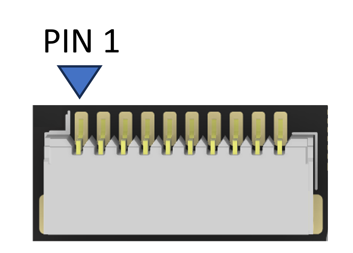
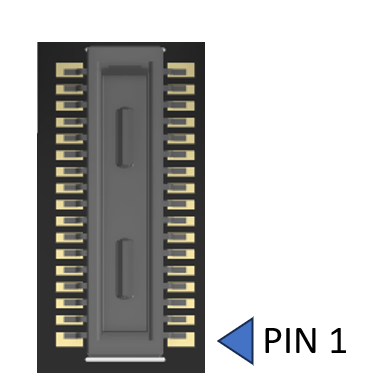
Board-to-Board Connector – DF40C-30DP-0.4V(51)
-
Connector Definition
Type Part Number Series Manufacturer Board Connector DF40C-30DP-0.4V(51) DF40 Hirose Mating Connector DF40C-30DS-0.4V(51) DF40 Hirose - Orientation note:
- This rotated layout places Pin 1 at the bottom-right, as viewed from the top-down PCB perspective (connector facing up).
- Even pins run upward along the left column.
- Odd pins run upward along the right column.
- Orientation note:
-
Connector Pinout
Notes Signal Pin • Pin Signal Notes 5V 30 • 29 5V 5V 28 • 27 5V GND 26 • 25 USB4_D_P USB HS GND 24 • 23 USB4_D_N USB HS GND 22 • 21 GND GPIO16 (3.3 V) GPIO16 20 • 19 USB3_D_P USB HS GPIO15 (3.3 V) GPIO15 18 • 17 USB3_D_N USB HS GPIO15 (3.3 V) GPIO14 16 • 15 GND GPIO13 (3.3 V) GPIO13 14 • 13 USB2_D_P USB HS GPIO12 (3.3 V) GPIO12 12 • 11 USB2_D_N USB HS GPIO11 (3.3 V) GPIO11 10 • 9 GND GPIO10 (3.3 V) GPIO10 8 • 7 USB1_D_P USB HS GPIO9 (3.3 V) GPIO9 6 • 5 USB1_D_N USB HS GND 4 • 3 GND GND 2 • 1 GND
GPIO_B Connector
-
Connector Definition
Type Part Number Series Board Connector SM10B-SRSS-TB JST-SH Cable Connector SHR-10V-S-B JST-SH -
Connector Pinout
Pin Name Description 1 5V Power output (5 V) 2 GPIO9 GPIO 9 (3.3 V) 3 GPIO10 GPIO 10 (3.3 V) 4 GPIO11 GPIO 11 (3.3 V) 5 GPIO12 GPIO 12 (3.3 V) 6 GPIO13 GPIO 13 (3.3 V) 7 GPIO14 GPIO 14 (3.3 V) 8 GPIO15 GPIO 15 (3.3 V) 9 GPIO16 GPIO 16 (3.3 V) 10 GND Ground
USB Connector
-
Connector Definition
Type Part Number Series Board Connector SM10B-SRSS-TB JST-SH Cable Connector SHR-10V-S-B JST-SH -
Connector Pinout
Pin Name Description 1 5V Power output (5 V) 2 USB1_D_N 3 USB1_D_N 4 USB2_D_N 5 USB2_D_N 6 USB3_D_N 7 USB3_D_N 8 USB4_D_N 9 USB4_D_N 10 GND Ground
Software
Drivers & Support
- Compatible with FTDI VCP and D2XX drivers
- Supported on Windows, Linux, and macOS
- Fully programmable via FTDI MPSSE
Example Code
- gpio control